Advanced cell simulation for passive- and active-balancing BMS testing
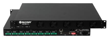
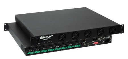
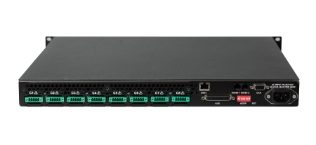
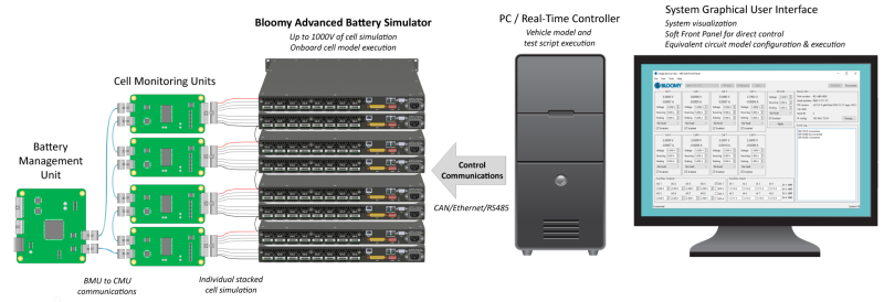
The Advanced Battery Simulator 800 (ABS) provides eight 5V, 5A cells to simulate battery sink and source characteristics for testing Battery Management Systems (BMS). Over 200 cells can be stacked in series to safely simulate battery stacks of up to 1000 VDC. Built-in voltage and current readback sensing per cell provide highly accurate simulation as well as live data readings without external monitoring equipment. Onboard auxiliary I/O can be used to simulate cell and module temperature sensors and provides additional analog and digital I/O. Integrated faulting relays facilitate open circuit, cell short, and reverse polarity faults, with a dedicated "BMS" output line to ensure faulting does not break the cell stack. Safe operation is guaranteed by certification to the IEC 61010 product safety standard and the use of robust, reinforced/double insulation between the high voltage cell domains and the low voltage communication interfaces and auxiliary IO domains.
- 8 independently controlled cell channels
- 0 to 5 VDC output, sink/source up to 5A/Ch
- <0.5mV voltage accuracy
- 1000 VDC Ch-to-Earth GND isolation
- 1000 VDC Ch-to-Ch isolation
- 1U form factor for high cell density
- Certified to IEC 61010-1, -2
- Built-in fault insertion per cell (open, short, reverse polarity)
- Dedicated BMS terminal per cell
- Auxiliary ±10V analog and 5V digital I/O
- Voltage-based temperature simulation per cell
- TCP/IP, UDP, RS-485, and high-speed CAN control communications
- C/C++, Python, & NI LabVIEW™ drivers
- CAN .dbc file
- Onboard cell equivalent circuit modeling
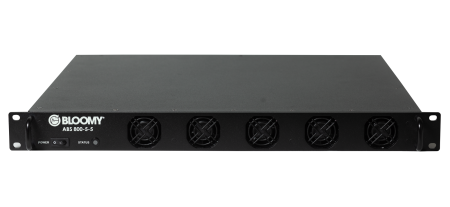
The Advanced Battery Simulator 800 (ABS) is BLOOMY’s next generation battery cell simulator (aka emulator) for testing battery management systems (BMS) and other battery-sensitive devices for EVs, electric aircraft, stationary ESS and more! Its best-in-class performance includes sub-1mV cell voltage accuracy across its 0-5V range, extremely low noise, 5A of current sink/source capability per cell, integrated short, open, and polarity-reversed cell faults, cell temperature and pack current sensor simulation, and 1,000V of reinforced isolation. In addition, the ABS performs onboard cell model execution with kilohertz loop rates, and has an intuitive SCPI application programming interface. The ABS is remotely monitored and controlled via Ethernet, CAN, and RS-485 using the included software drivers for C/C++, CAN DBC, Python, NI LabVIEW™, and more.
Onboard cell model execution facilitates distributed, asynchronous execution across multiple instruments, allowing virtual unlimited scaling of battery hardware-in-the-loop (HIL) simulator applications. By combining the simulated cells, models, faulting, and sensors onboard the ABS, as well as the ability to series-connect multiple instruments, the ABS cohesively and comprehensively simulates a battery with minimal supervision from a host computer. The dense feature set in a modular 1.75" (1RU) package makes BLOOMY’s ABS the most advanced battery simulator now available!
Learn more about Bloomy’s complete BMS test offerings:
| Cell Channel Features (per channel unless otherwise noted) | |
|---|---|
| Isolated Channels | 8 |
| Operation Modes | Constant Voltage or Constant Current Sourcing or Sinking |
| Voltage Range | 0 to 5 VDC |
| Current Ranges | ±1A or ±5A |
| Remote Sensing | 4-Wire Voltage Compensation |
| Working Voltage | 1000 VDC Ch-to-Earth GND (reinforced/double), Ch-to-Ch (basic) |
| Withstand Voltages | Ch-to-Earth: 2780 VAC for 5 sec, 2000 VDC for 60 sec Ch-to-Ch: 1680 VAC for 5 sec |
| Fault Insertion | Open, Short, Reverse Polarity |
| Protection | OVP, OCP, OPP |
| Calibration Interval | 2 Years |
| Cell Channel Performance (typ. @ 22°C ± 2°C) | |
|---|---|
| Voltage Setpoint | ±0.75mV Accuracy, 105μV Resolution |
| Current Limits | ±20mA Accuracy, 105μA Resolution |
| Control Loop Rates (selectable) | 1kHz (fastest) |
| Voltage Read Accuracy | ±0.48mV @ 4V Output |
| Current Read Accuracy | ±1A Range: ±0.6mA ±5A Range: ±2.4mA |
| Voltage Read Resolution (includes pk-pk noise) | 55μV @ 1kHz Control 10μV @ 10Hz Control |
| Current Read Resolution (includes pk-pk noise) | ±1A Range: 135μA @ 1kHz Control, 10μA @ 10Hz Control ±5A Range: 695μA @ 1kHz Control, 55μA @ 10Hz Control |
| Voltage Step Response | 50μs (10% to 90%) 1ms (settled to < 1mV) |
| Load Step Response | 30μs (transient recovery) 1ms (settled to < 1mV) |
| Auxiliary I/O | |
|---|---|
| Analog Outputs | 8 channels, 16-bit, ±10 VDC, 5mA |
| Analog Inputs | 8 channels, 16-bit, ±10 VDC |
| Analog I/O Update Rate | 100Hz |
| Digital Outputs (general purpose) | 4 Channels, 5V, 5mA |
| Digital Inputs (general purpose) | 4 Channels, 3.3V or 5V |
| Digital I/O Update Rate | 1kHz |
| Inhibit | 1 TTL Input (shuts down all cell simulation channels) |
| Communications | |
|---|---|
| Interfaces | TCP/IP, UDP, CAN, RS-485 |
| Max Command / Read Rate | 400Hz (TCP, UDP), 100Hz (CAN), 50Hz (RS-485) |
| Software | C/C++, Python, NI LabVIEW™, CAN .dbc, VeriStand™ Integration |
| Physical / Environmental | |
|---|---|
| Power Input | 100-264 VAC, 50/60Hz |
| Dimensions | 483 mm W x 424 mm D x 43.95 mm H (suitable for 1U 19” racks) |
| Weight | 7.94 kg (17.5 lbs) |
| Operating Temp / Humidity | 0°C to 35°C, 20% to 85% RH |
| Pollution Degree | 2 |
| Compliance | |
|---|---|
| Safety | CB Ref. No. US/10671/ITS IEC 61010-1:2010 / AMD1:2016 IEC 61010-2-030:2017 |
| EMC | EN 55011, EN 61000, EN 61326 FCC Part 15 ICES-001 |
| Environmental | RoHS, REACH |
| CE | 2014/35/EU; Low-Voltage Directive 2014/30/EU; Electromagnetic Compatibility Directive (EMC) 2011/65/EU; Restriction of Hazardous Substances (RoHS) |
The Advanced Battery Simulator 800 (ABS) can be used as a standard instrument, controllable via TCP/IP, UDP, CAN, or RS-485 via the supplied C/C++, Python, LabVIEW™ drivers. The ABS can also be integrated into hardware-in-the-loop (HIL) and real-time environments using the supplied CAN .dbc files. Whether controlled via standard SCPI commands for automated production test, or via real-time CAN for HIL validation, the ABS is the fundamental building block of many advanced BMS automated test solutions.
Do you have a specific application? Contact us.
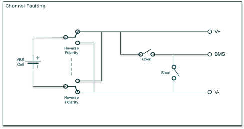
The Advanced Battery Simulator 800 (ABS) introduces a new level of flexibility and safety to the laboratory environment with built-in fault modes for each cell! Each of the ABS’s simulated cells has one normal state and three fault states:
Normal: In normal operation, all terminals of each cell remain connected. The battery management system (BMS) or other unit under test is able to sense each cell’s state and to control cell balancing and other pack characteristics.
Open-Wire: During an open-wire fault state, the ABS physically disconnects the simulated cell’s battery management system terminal. This fault simulates the real-world condition of a broken sense wire. The simulated battery pack’s other connections may or may not remain intact during this fault depending on how the BMS and ABS are connected.
Short-Circuit: The short-circuit fault state causes the ABS to apply a physical short circuit between the cell’s negative terminal and the cell’s BMS terminal. This condition may arise, for example, through abrasion or when insulation melts in an overheated battery pack.
Reverse Polarity: The ABS reverses the polarity of the simulated battery cell when the cell is in this fault condition. A battery can acquire a negative polarity if the BMS has allowed a completely discharged cell to become charged by other cells, thus acquiring a negative charge.
Using the built-in faulting capability of the ABS ensures the utmost safety and reliability of your product.
| Accessory | P/N | Description |
|---|---|---|
| Power Cord Included with unit | Qualtek 312008-01 | Power Cord Black NEMA 5-15P to IEC 320-C13 SJT, 7.5ft, UL, cUL |
| Cell Connectors 8x included with unit | Sauro DBF050D8 (Bloomy 3310-00664) | Pluggable terminal block, 5 position, spring tightening, 3.5mm pitch, 600 CTI |
| Ferrite Clamps 8x included with unit | Laird 28A0593-0A2 | Ferrite clamp for EMC suppression on cell connectors |
| Cell Cable Kit (4-wire) | 2900-00173 | Kit of 8x 4-wire cell interface cables, 1M long |
| Cell Stacking Harness | 2500-00860 | Harness for stacking 8x cell of an ABS, with connectivity for stacking to additional units |
| Rear Safety Cover | 2900-00141 | Safety cover for rear cell connectors to provide strain relief and restrict access to high voltage cell cables. Required for applications exceeding 160 VDC unless individual cell backshells are installed. |
| Cell Connector Backshells Kit | 2900-00146 | Kit of 8x individual backshells for cell connectors. Required for applications exceeding 160 VDC unless rear safety cover is installed. |
| CAN Daisy Chain Cable Kit | 2900-00171 | Cable kit for daisy-chain CAN communications for up to 4 ABS units |
| RS485 Daisy Chain Kit | 2900-00174 | Cable kit for daisy-chain RS485 comminications for up to 4 ABS units. |
| Aux I/O Breakout Kit | 2900-00172 | HD44 breakout board with 1M cable |
Documentation
Advanced Battery Simulator 800 Quick Start Guide
Advanced Battery Simulator 800 User Manual
Advanced Battery Simulator 800 SCPI ICD
Advanced Battery Simulator 800 CAN ICD
Advanced Battery Simulator 800 Critical Safety Notice
Drivers
Advanced Battery Simulator 800 SCPI Driver
Advanced Battery Simulator 800 SCPI Python Driver
Software
Advanced Battery Simulator 800 Soft Front Panel

