
A safe, efficient test stimulus for HIL validation of high-voltage systems
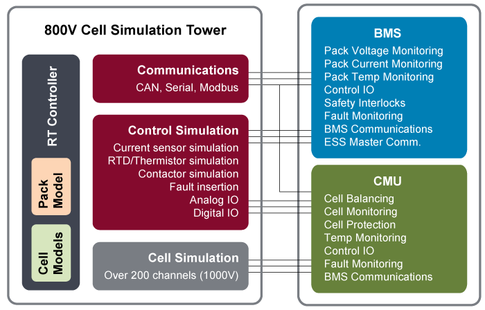
The 800V Cell Simulation Tower is an electronic functional equivalent of an 800V battery pack, without the hazards and inefficiencies of real battery cells. An accurate and repeatable test stimulus, the 800V Cell Simulation Tower may be used for hardware-in-the-loop (HIL) testing of battery management systems (BMSs), or combined with a BMS to form a battery surrogate for testing and validating many battery-sensitive systems.
- Electronically simulates the cells, thermistors, contactors, pre-charge circuits, sensors, taps, and
communications of an 800V battery pack - Provides near-instantaneous SOC changes
- Optionally executes real-time models to control the simulated pack state
- Simulate drive cycles, load profiles, alarms, fault case scenarios, and cell ageing
- Integrates CMUs and a BMS within the same enclosure
The 800V Cell Simulation Tower provides full, immediate control of the BMS without the delays and hazards inherent with charging and discharging real battery cells. It is a musthave for every electrification test lab!
Applications include:
- Testing Chargers, Inverters, and Power controls
- Energy Management Systems
- Automotive Electronic Controls (ECUs)
- Aerospace Line Replaceable Units (LRUs)
- Vehicle Simulators
- Iron Birds
Need a portable system for simulating 12-36 cells?
Inquire about the Desktop BMS HIL Test System.
The 800V Cell Simulation Tower is a modular platform, providing a unique configuration to test individual BMS devices and functionality.
The 800V Cell Simulation Tower benefits include:
- Accurate and repeatable test stimulus
- Increased test coverage beyond the safe operating region of a real battery
- Does not require chemical fire suppression
The following specifications are standard. Systems can be customized to accommodate your requirements.
| Cell Channel Simulation | |
|---|---|
| Number of Channels | 12 / module |
| Max number of Modules | 20 (240 channels @ 4.2V) |
| Channel Type | Sink and Source |
| Voltage Range per cell | 0.0 to 5.0V |
| Voltage Resolution | 0.1 mV |
| Voltage Accuracy (Requires Remote Sense) | ±1 mV |
| Balancing Current Range* | ± 500.0 mA; output derates linearly under 2 V |
| Current Resolution | 0.1 mA |
| Current Limiting Accuracy | ±10 mA |
| Common Mode Isolation | 1000 VDC reinforced/double |
| Cell Channel Readback | |
|---|---|
| Voltage Resolution | 0.1 mV |
| Voltage Accuracy | ±1 mV |
| Current Resolution | 0.1 mA |
| Current Accuracy | ±1 mA |
| Temperature Sensor Simulation | |
|---|---|
| Typical Signal Type* | Voltage Resistance |
| Number of Channels | 4 to 240 |
| Range | ±10V 2.5Ω – 1.5MΩ |
| Resolution | <1 mV 2Ω |
| Accuracy (typical) | 0.03% 0.2% |
| Current Sensor Simulation | |
|---|---|
| Typical Signal Type | Analog voltage |
| Number of Channels | 2 to 4 |
| Range | ± 10V |
| Resolution | 16 bit |
| Accuracy | ± 0.5% |
| Additional Signal Types | CAN communications, Bidirectional Power Supply |
| Communication Protocols | |
|---|---|
| Standard Protocol | High-speed CAN |
| Number of Ports | 2 |
| Baud Rate | 40 kbits/s to 1 Mbit/s |
| Additional Protocols | LIN, SPI, RS232, Modbus |
| Pack Voltage Simulation | |
|---|---|
| Number of Channels | 1 to 10 |
| Voltage Range* | Up to 1000 VDC |
| Output Power | 5W 30W 1500W |
| Resolution | 0.1V 0.1V 0.003V |
| Accuracy (typical) | 1-2% 1-2% 0.075% |
| Pack Power Emulation | |
|---|---|
| Number of Channels | 1 to 2 |
| Voltage Range* | Up to 1200 VDC |
| Output Power | 200W to >500kW |
| BMS Control IO | |
|---|---|
| Number of Channels | Up to 32 input / 32 output |
| Voltage Range | 0 to 30V |
| Current Drive | Up to 150 mA |
| Common Mode Isolation | 30V bank-to-bank |
* Do you have special requirements for cell, bus, or pack voltage or current; isolation, temperature simulation, or communications? Contact us.
The 800V Cell simulation tower may be configured to run stand-alone, either through direct IO control or model-based execution. A Graphical User Interface allows engineers to interact with instrumentation and model parameters, and automated test environments provide the ability to script test scenarios for basic functional testing, or advanced real-time drive cycle execution. In addition, the system may be connected to external third party software for integration into existing Hardware-In-the-Loop (HIL) or continuous integration environments. Because all BMS units are unique, Bloomy has developed system level components to facilitate platform scalability and supportability to reduce software customization. Major application features:
- Graphical User interface: to ensure you get the most out of the system, a customized interface is provided to view full system status and perform all system control, test, report viewing, and configuration.
- Manual Control: complete operation of system channels and allows for value forcing, alarming, calibration, and stimulus generation.
- Model Execution: save, recall, and load battery cell and pack chemistry models. Model execution is dependent on system IO, channel count, feedback, and the model itself. Typical pack model execution (complete system IO) is between 10Hz and 1000Hz.
- Automated Test: fully automated test environment, providing the ability to generate stimulus profiles (drive profiles) and test scenarios to complete BMS firmware regression testing.
- Communication Integration: integrate standard CAN and LIN automotive diagnostics or implement custom communication protocols used as feedback into models or measurement and reporting channels.
- Reporting: create test reports for system IO, communication capturing during manual or automated control.
- System Configuration: store all necessary hardware configuration information, software variables, IP address, report folders, model location, test stimulus profiles, and other critical station information.