What Makes a DDS Engine?
Design Guidelines – Sample Table
The Sample Table is going to contain all the possible outputs for the DDS engine. The Sample Table is represented by a Memory item in an FPGA project. If the LabVIEW version is old enough, it may be necessary to use a fixed length array instead. At the start of the FPGA application, initialize the Sample Table with a known waveform. For the purposes of this article, it's presumed that the data in the Sample Table will be 1 cycle of a sinusoid with 1 Volt amplitude. This waveform will need to be sampled to the size of the Sample Table. This is an important decision point. The size of the Sample Table, in conjunction with some other parameters, dictates the maximum precision of the output data. The DDS engine is only capable of outputting samples that can be found in the Sample Table. A small table is more resource efficient, but may result in poor waveform shape and features when attempting to produce a high-frequency output. To select an effective Sample Table size, review the customer documentation to determine precision requirements, the minimum number of samples per cycle, and the Source Clock rate. A proper understanding of these properties will assist in selecting a proper Sample Table size. Typically the Sample Table is prefilled with data, but external mechanisms may modify the Sample Data content as necessary to further customize the output generation.
Example: Basic Sinusoid Output
Requirements: Output up to 100kHz waveform (sinusoid) with at least 64 samples per cycle.
Source Clock: 10MHz
Sample Table Size: At least 64 Samples
Rationale: In this case, we know the upper limit for representable frequencies. We can just assume that we will never need to go faster than 64 samples for a 100kHz waveform. However, one important takeaway, a 10MHz Source Clock will only allow for for a maximum samples/cycle of 100 for a 100kHz frequency requirement. The Source Clock rate would need to be increased to allow for more precise output generation. See the Source Clock section for more information.
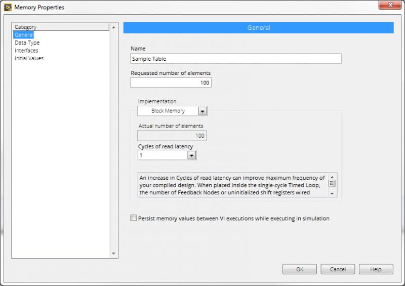
Figure 1. Sample Table Memory Configuration Dialog
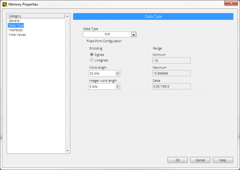
Figure 2. Sample Table Memory Data Type Dialog
Always make the Sample Table data type match the actual analog output type.
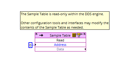
Figure 3. Sample Tables Are Just Memory Items
Select the index and write the data output to the target analog output.
Design Guidelines – Source Clock
The Source Clock is responsible for clocking the DDS engine. Every time the Source Clock ticks, the DDS engine will execute once. During a single execution, the DDS engine will increment the Accumulator by the Tuning Word value, select a new output value from the Sample Table, and output that value on hardware. Additionally, the Source Clock will dictate the maximum precision an output waveform can achieve through the DDS engine. The Sample Clock should be set to the highest necessary value to fulfill the documented signal generation requirements. Selection of a Source Clock is usually fairly strict, compared to selecting a Sample Table. Most National Instruments FPGAs have an inherent limit of 40MHz clocking, without using a clock multiplier (which is generally inadvisable to use for a DDS engine). This limitation means that it's best to set the Source Clock to a high rate and adjust the Sample Table as necessary to achieve the minimum sampling requirements.
Example: Basic Sinusoid Output
Requirements: Output up to a 50kHz waveform (sinusoid) with at least 100 samples/cycle.
Sample Table: 100 Samples
Source Clock: At least 5MHz
Rationale: In this example, the Sample Table is fixed. The Source Clock needs to be set to a particular rate to achieve the desired waveform output. Simply take the samples/cycle requirement and multiply it against the maximum required frequency. That will produce the minimum required rate for the Source Clock.
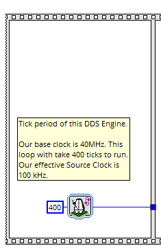
Figure 4. The Source Clock Synchronization is Maintained in the First Frame of a Sequence Structure
This should always be defined in tick counts for maximum flexibility.
Design Guidelines – Tuning Word
The Tuning Word is what allows a DDS engine to produce an exceptionally wide variety of waveforms, using only a single Sample Table. The Tuning Word dictates how many samples are transitioned during single execution of the DDS engine. When the value of the Tuning Word is set to a variety of values, different basic behaviors can be classified:
- Tuning Word equals 1: The DDS engine should visit every sample in the Sample Table once as it executes. Essentially, each tick of the Source Clock will produce a new output value every time. This will always produce a fixed output frequency based on the size of the Sample Table and therate of the Source Clock.
- Tuning Word greater than 1: The DDS engine will routinely skip samples to produce a higher frequency output. The Tuning Word may be a decimal value. The Accumulator will handle that decimal to account for drift.
- Tuning Word less than 1: The DDS engine will routinely revisit the same sample on consecutive executions of the DDS engine to produce a lower frequency waveform. The Tuning Word may be a decimal value. The Accumulator will handle that decimal to account for drift.
To generalize, adjusting the Tuning Word will result in various different output frequencies, assuming a single cycle of a sinusoid is present in the Sample Table. The tuning word should always be a floating point or fixed point value to allow for precise frequency selection. Please note that a fixed point value that is not sufficiently accurate will result in unmanaged frequency inaccuracies, but may allow for higher operating speeds.
Example: Basic Sinusoid Output
Requirements: Output any sinusoidal frequency from 10kHz to 50kHz with at least 100 samples/cycle.
Sample Table: 100 Samples
Source Clock: 10MHz
Tuning Word Range:
- 10kHz = 0.1
- 33kHz = 0.33
- 50kHz = 0.5
Math: TuningWordValue = (TargetFrequency * SampleTableSize) / (SourceClockRate)
Rationale: This is just simple execution of the equation in the math section. Due to the high Source Clock rate, the Tuning Word is always smaller than 1. If the Source Clock was set slower or the Sample Table was larger, the Tuning Word could go above 1.

Figure 5. The Tuning Word is Literally Just a Value That Allows the Controller Software to Adjust the Output Behavior of the DDS Engine
It can be replaced with a register in the event that the DDS behavior is in subVI.
Design Guidelines – Accumulator
As seen in prior sections, the Tuning Word is designed to accept floating-point and fixed-point values. This is an intentional design choice. If the Tuning Word was an integer, it would cause serious long-term issues with the flexibility of the DDS engine (I strongly suggest trying this at a later point and seeing what happens). Regardless, the addition of a decimal place will cause some serious issues when trying to access Sample Table entries. Without handling the error accrued by that decimal place, the DDS engine will only produce specific frequencies that can be represented by the coerced integer indexes on every iteration. Additionally, the DDS engine would never be able to represent output waveform frequencies that are represented by Tuning Words that are less than 1. Since that would be completely unacceptable, the Accumulator is introduced as the final component of the DDS engine. The Accumulator exists to accumulate the current value of the Tuning Word every execution of the DDS engine. In other words, it's a value that has the Tuning Word added to it over and over again. Using the prior example at 10kHz, a couple DDS engine executions would look like this:
- Execution 0: Accumulator(t) = 0 + TuningWord = 0.1
- Execution 1: Accumulator(t+1) = Accumulator(t) + TuningWord = 0.2
- Execution 2: Accumulator(t+2) = Accumulator(t+1) + TuningWord = 0.3
- Execution 3: Accumulator(t+3) = Accumulator(t+2) + TuningWord = 0.4
... and so on... note that all the above values will still access index 0 in the Sample Table. All discussion here will assume a floor operation to reach integer values. Samples are output after each accumulation.
As the Accumulator increments, a copy of the Accumulator value is coerced to an integer value, which will be used to access an index in the Sample Table. The retrieved sample is then output. Once the Accumulator reaches the maximum representable sample in the Sample Table, it needs to handle a rollover event. To explain this further, the current value of the Accumulator represents an index for a value in the Sample Table. If it represents an index that doesn't exist, there will be a runtime error or an incorrect value will be output. To prevent this from happening, the Accumulator is aware of the maximum size of the Sample Table. Once it reaches a value that will exceed the maximum size of the Sample Table, it will subtract the size of the table from the current Accumulator value, retain the remaining decimal (we cannot lose this value or the engine will drift). For example:
- Execution 999: Accumulator(t+999) = Accumulator(t+998) + TuningWord = 100
- Rollover event triggered: Accumulator(t+999) = Accumulator(t+999) - 100 = 0
- Sample is output from index 0 in Sample Table
- Execution 1000: Accumulator(t+1000) = Accumulator(t+999) + TuningWord = 0.1
The behavior of rollover events is critical to ensuring the DDS engine does not drift and represent an incorrect output frequency.
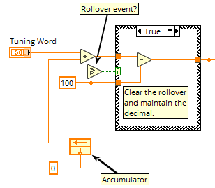
Figure 6. A Working Accumulator
The false case of the case structure will just pass the current accumulator value through.
Advantages/disadvantages
DDS Engines are extremely useful and powerful, however they are also very expensive to implement and debug. It's important to realize the strengths and pitfalls of this tool before attempting to leverage in an application:
Advantages
- Extremely accurate output generation
- Allows for seamless sample transitions
- Supports linear and non-linear frequency sweeping
- No need to operate around zero-crossing points.
Disadvantages
- Expensive to implement. Can use a lot of FPGA resources.
- Difficult to debug and test
- High frequency images: Since all the waveform generation is 'digital', all the output waveforms will carry high-frequency harmonics of the Source Clock. these are observable in power spectrum analysis. You need a high frequency low-pass filter to get rid of them. Usually not an issue, but it can have a notable impact on very specific applications.
- You need an FPGA to make one.
Example Implementation
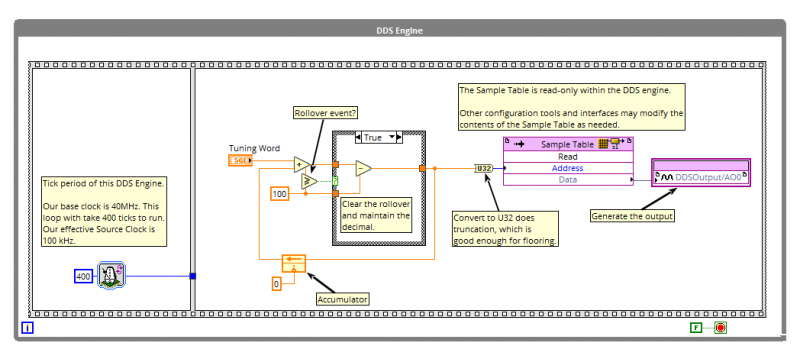
Figure 7. A Basic DDS Engine Using a 40MHz FPGA Reference Clock
Stay tuned for Part III on Direct Digital Synthesis!
Modifying the DDS Engine
- Time-Variant DDS
- Non-Sinusoidal Data
- Resources
Related Links
- ryanvallieres's blog
- Log in or register to post comments
